To create a rock-solid chassis ground and eliminate noise, avoid connecting multiple chassis points, which can cause ground loops and interference. Instead, use a single-point, star configuration for grounding, and guarantee all wires are properly sized and securely connected. Keep signal and ground paths short and use continuous ground planes on your PCB. Proper grounding also involves regular testing and avoiding shared grounds that introduce unwanted currents. Keep exploring for more tips to achieve a perfectly quiet system.
Key Takeaways
- Connect the chassis to system ground at only one point to prevent ground loops and reduce noise.
- Use a star topology for grounding, ensuring all ground connections converge at a single, low-impedance point.
- Employ thick, stranded copper wire (e.g., 14 AWG) for flexible, reliable, and low-resistance chassis grounding.
- Utilize continuous ground planes on PCBs and place bypass capacitors close to ICs to minimize noise and ground bounce.
- Regularly test ground connections for low voltage drops and ensure tight, corrosion-free contacts for consistent performance.

Alphastat Table Mat Grounding Kit – Universal Snap Kit and 15' 1 Meg Male Low Profile Ground Cord
TABLE MAT GROUND: A complete kit to install and ground ESD and Anti-Static table mats according to ANSI…
As an affiliate, we earn on qualifying purchases.
As an affiliate, we earn on qualifying purchases.
Debunking Common Grounding Misconceptions
Many common grounding myths stem from misconceptions about how grounding actually works in electronic systems. One widespread belief is that connecting multiple chassis points improves safety and noise reduction. In reality, multiple connections can create ground loops, allowing noise to flow through low-impedance paths and cause interference. Another myth is that thicker wires always mean better grounding; while thicker conductors reduce resistance, proper layout and single-point connections are more important for noise suppression. Some think chassis grounding is only for safety, but it also helps prevent floating voltages and electromagnetic interference. Understanding that chassis ground should be connected at one point, with careful design, is vital. Proper grounding practices focus on minimizing loops, controlling impedance, and ensuring a reliable, noise-free system. Additionally, European cloud innovation emphasizes the importance of sustainable and secure grounding practices in modern data centers. Proper grounding also involves understanding the grounding impedance, which influences the effectiveness of noise reduction strategies. Moreover, considering the grounding system layout can significantly enhance overall system stability and noise immunity.

THHN Wire 14 Gauge 25 FT Stranded Copper Wire, 14 AWG Copper Wire Rated up to 600V Building Wire Nylon Jacket for Residential, CNC, Ground, Industrial (14 Gauge, Green)
THHN wire has good heat resistance, stable operation at high temperatures and improve the instantaneous thermal overload resistance…
As an affiliate, we earn on qualifying purchases.
As an affiliate, we earn on qualifying purchases.
The Benefits of Single-Point Chassis Grounding

Single-point chassis grounding offers significant noise reduction benefits by establishing a dedicated, low-impedance connection between your device’s metal enclosure and system ground. This setup prevents multiple ground paths that can cause ground loops and introduce hum or interference. By connecting the chassis at one point only, you minimize the risk of noise currents flowing through your signal grounds, which can distort signals or generate unwanted noise. This ground loop prevention is essential for maintaining signal integrity in sensitive electronic systems. Proper implementation of grounding techniques can further enhance noise suppression and system stability. This approach helps contain electromagnetic interference and reduces EMI/RFI emissions, creating a more stable and cleaner environment for sensitive circuitry. Additionally, a single connection simplifies troubleshooting and ensures consistent grounding, leading to improved overall performance. Properly implementing single-point chassis grounding ensures your device remains quiet, stable, and free from noise-induced drama. Incorporating a proper grounding technique is essential to maximize these benefits and achieve optimal performance.

Hakko CHP DP-20-N Depaneling Tool, Printed Circuit Board (PCB), 2.0mm Width, 2.5mm Isthmus Cut, 40kg Cutting Force
Depaneling tool separates printed circuit boards (PCB) in multiple circuit board production
As an affiliate, we earn on qualifying purchases.
As an affiliate, we earn on qualifying purchases.
Proper Wire Sizes and Materials for Reliable Ground Connections
Choosing the right wire size and material is essential for reliable ground connections. Stranded wire offers lower resistance and better flexibility than solid wire, making it ideal for grounding loops. Make certain to select conductors like copper or tinned copper to guarantee good conductivity and durability. Additionally, understanding the net worth of notable figures can help you appreciate the value of quality materials in high-performance applications. Using appropriately rated wires also minimizes the risk of overheating and electrical failures, which is crucial for maintaining grounding integrity. Proper installation techniques, such as ensuring tight connections and corrosion resistance, also play a vital role in sustaining a grounded system that performs reliably over time. Recognizing the importance of material properties can further optimize your grounding setup for longevity and safety.
Stranded vs. Solid Wire
Using stranded wire instead of solid wire is essential for guaranteeing reliable ground connections, especially in applications requiring flexibility and vibration resistance. Stranded wire maintains good contact despite movement, preventing intermittent connections that can cause noise or failure. Solid wire, while easier to crimp, can fatigue or break under vibration, leading to increased resistance. The table below highlights key differences:
| Feature | Stranded Wire | Solid Wire |
|---|---|---|
| Flexibility | High | Low |
| Vibration Resistance | Excellent | Poor |
| Ease of Termination | Slightly more complex | Easier |
| Durability | Longer lifespan in dynamic setups | Shorter lifespan in vibrations |
Choosing stranded wire guarantees your grounding remains solid and noise-free over time. For optimal performance, understanding nanotechnology principles can help improve material selection and connection reliability in advanced electronic systems.
Appropriate Conductive Materials
Selecting the right conductive materials and wire sizes is essential for ensuring reliable ground connections. Use stranded copper wire at least 14 AWG for ground distribution loops to minimize resistance and impedance. Stranded wire offers greater flexibility and lower inductance compared to solid wire, which helps reduce noise and voltage drops. Always choose copper over aluminum for better conductivity and durability. Avoid thin or undersized wires that can overheat or cause voltage irregularities, risking noise and connection failure. Use heavy-gauge wire to handle fault currents safely and maintain low resistance. For connecting board GND to chassis, utilize metal spacers and appropriately rated connectors. Ensuring proper materials and sizes prevents voltage drops, reduces electromagnetic interference, and guarantees a stable, low-impedance ground system.

VIBICCK 24 Values 400 Pcs Aluminum Electrolytic Capacitors Assortment Kit SMD Bypass Low Frequency Aluminum 1uF – 1000uF
There are 24 types: 24 different models of SMD electrolytic capacitors, with 400 different capacities (ranging from 1…
As an affiliate, we earn on qualifying purchases.
As an affiliate, we earn on qualifying purchases.
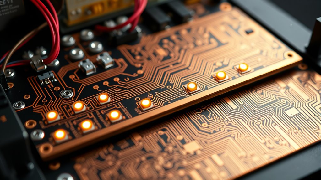
PCB Layout Strategies to Minimize Ground Noise

Effective PCB layout is essential for minimizing ground noise and ensuring stable operation. To achieve this, use continuous ground planes to provide low-impedance return paths and suppress ground bounce. Place bypass capacitors as close as possible to IC supply pins, and connect them with short, wide traces to reduce inductance. Incorporate via-in-pads and add vias near capacitor pads to improve high-frequency performance. Keep signal return paths short and direct, avoiding long traces that can pick up noise. Use multilayer ceramic capacitors (MLCCs) for better high-frequency filtering. Separate signal ground from chassis ground, connecting them at a single point with a high-resistance resistor and capacitor. Don’t share ground vias or traces among different circuits, and maintain proper via placement to prevent ground loops. Proper grounding techniques are vital for minimizing electromagnetic interference and ensuring reliable operation. Additionally, grounding topology plays a crucial role in achieving optimal noise performance. Employing a well-designed grounding strategy can significantly reduce the potential for noise coupling and improve overall system stability. Implementing grounding techniques tailored to high-current and sensitive signal areas can further enhance the effectiveness of your ground layout. Additionally, paying attention to grounding best practices can help prevent common issues such as ground loops and interference.
Avoiding Ground Loops and Unwanted Current Paths

To prevent ground loops, you need to connect your chassis to system ground at only one point, avoiding multiple paths that can introduce noise. Proper wire management, such as using the right gauge and avoiding shared ground traces, helps keep unwanted currents from flowing through signal circuits. Always make certain you don’t create multiple ground paths, which can lead to interference and degraded performance. Incorporating smart home gym equipment can also help monitor and optimize your grounding setup for better performance. Paying attention to grounding best practices ensures your system remains stable and free of disruptive noise. Additionally, understanding Gold IRA markets can help you make informed decisions to protect your investments during system upgrades or maintenance. Being aware of vintage audio wiring techniques can further enhance your grounding strategy and preserve audio fidelity. Recognizing essential oils for noise reduction can also provide a calming influence in complex electronic environments, helping to minimize interference.
Single-Point Connection Importance
A single-point connection is crucial because it prevents ground loops that can introduce noise and interfere with circuit operation. When multiple ground connections exist, currents can circulate unintentionally, creating hum, interference, or signal distortion. By connecting the chassis to system ground at just one point—such as a dedicated pin—you ensure a clean, stable reference without unwanted current paths. This “star” configuration steers noise currents away from sensitive signal circuits and reduces electromagnetic interference. It also helps maintain consistent voltage levels across your system, avoiding fluctuating potentials that cause noise. Always evaluate your chassis grounding setup case-by-case, but sticking to a single-point connection generally results in a quieter, more reliable system free of ground loop issues.
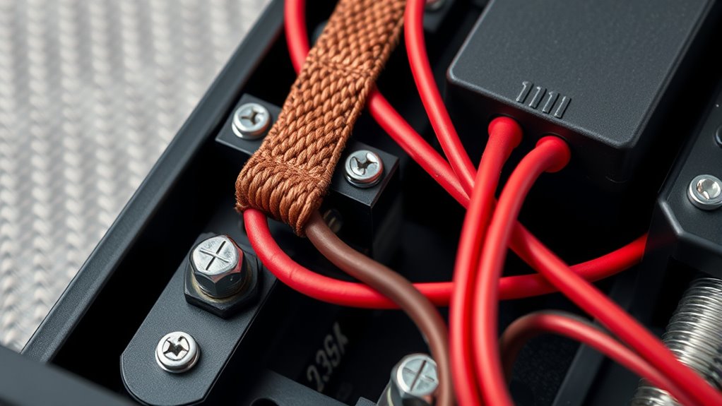
Proper Ground Wire Management
Proper ground wire management is essential to prevent ground loops and unwanted current paths that can introduce noise and compromise system stability. Keep ground wires short and direct, running them along a single path to minimize impedance. Use thick, stranded wires—14 AWG or heavier—to lower resistance and prevent voltage drops. Avoid daisy-chaining ground connections, which can create loops that pick up interference. Connect all grounds at a single point or through a star configuration, ensuring that no multiple paths exist between chassis and system ground. Secure wires neatly, preventing movement that might cause intermittent contact. Use proper connectors and consistent routing to reduce inductance. Regularly inspect wiring for corrosion or damage, maintaining a clean, reliable ground system that keeps noise at bay.
Avoid Multiple Ground Paths
Avoiding multiple ground paths is essential for maintaining signal integrity and preventing noise from entering your system. When multiple ground routes exist, unwanted current loops can form, causing hum, interference, and unstable operation. To visualize this, consider the following:
| Proper Grounding Setup | Problematic Ground Loop |
|---|---|
| Single-point connection | Multiple ground points |
| Star configuration | Parallel ground paths |
| Low-impedance chassis ground | Loops through signal ground |
Ensure all grounds connect at one point, typically using a star topology. This prevents currents from flowing through unintended paths, reducing noise and EMI. Use resistors and capacitors where necessary to isolate grounds. Proper grounding practices eliminate loops, ensuring your system remains quiet, stable, and free of disruptive interference.
Best Practices for Connecting Signal and Chassis Grounds

Connecting signal and chassis grounds correctly is essential to prevent noise issues and guarantee system safety. You should connect the chassis to the system ground at only one point, typically through a designated pin or connector. This single-point connection prevents ground loops that can introduce hum or interference. Avoid multiple connections, which allow noise currents to flow directly into sensitive signal circuits. Use a low-impedance connection, such as a thick stranded wire, to ensure minimal resistance. Keep the connection short and direct, ideally near the main ground point. Maintain a clear separation between signal ground and chassis ground, linking them with a high-value resistor and capacitor if needed. Proper grounding practices are also crucial for electromagnetic interference (EMI) mitigation. Additionally, understanding the grounding principles helps in designing systems that are resilient to noise and interference. Using proper shielding techniques and grounding strategies can further improve system performance and reduce susceptibility to external noise sources. Following these best practices helps reduce EMI, RFI, and noise coupling, ensuring a cleaner, safer system operation.
Verifying Ground Integrity Through Testing

Verifying ground integrity through testing guarantees your system’s safety and reliable operation. You should perform bond tests at 10-40A for a specified duration, ensuring the chassis and system ground are solidly connected. Use a dedicated ground tester or a high-current source with a precision ammeter to measure voltage drops across the ground path. Low readings indicate good conductivity and minimal resistance, confirming that fault currents will bypass sensitive circuitry. Regular testing helps identify loose connections, corrosion, or degraded conductors before they cause noise or safety issues. Be sure to test all critical ground points, especially after installation or maintenance. Proper verification ensures your chassis ground can handle fault conditions safely, preventing noise issues and protecting personnel and equipment.
Frequently Asked Questions
How Does Chassis Grounding Affect Electromagnetic Compatibility (EMC)?
Chassis grounding improves electromagnetic compatibility by providing a low-impedance path that contains electromagnetic emissions and reduces interference. When you connect your chassis properly, it acts as a shield, preventing external noise from affecting your device and minimizing radiated emissions. By maintaining a single-point ground and using appropriate grounding techniques, you help guarantee your system stays compliant with EMC standards, reducing noise, EMI, and RFI for cleaner operation and less interference.
Can Multiple Chassis Ground Connections Improve Overall System Safety?
Have you considered whether multiple chassis ground connections actually enhance safety? Generally, multiple connections can create ground loops that cause noise and potential safety hazards. To improve safety, you should connect the chassis to system ground at a single point, following proper grounding practices. This approach prevents unwanted currents and reduces the risk of electrical shock, ensuring your system remains both safe and reliable without introducing unnecessary noise or instability.
What Are the Risks of Improper Ground Testing Procedures?
You risk inaccurate test results and potential damage if you perform improper ground testing procedures. Using incorrect current levels or durations can cause overheating or stress on components, leading to false readings or system failure. Poor connections or neglecting safety protocols might expose you to electrical shock. Always follow manufacturer guidelines, confirm proper setup, and verify connections before testing to avoid costly mistakes and ensure reliable, safe grounding verification.
How Do I Select the Best Grounding Method for High-Frequency Circuits?
Did you know high-frequency circuits are 10 times more susceptible to noise? To select the best grounding method, use a single-point or star ground to prevent loops. Keep ground paths short with wide, stranded wires, and employ continuous ground planes. Connect sensitive components close to ground points, and avoid sharing vias or traces. Properly designed, your high-frequency circuits will experience less EMI and RFI, ensuring stable performance.
What Are Common Mistakes When Designing Ground Planes on PCBS?
You often make mistakes by splitting your ground planes, which creates loops and increases noise. Avoid sharing vias or traces for different grounds, as this disrupts continuity. Don’t place signal and chassis grounds together without proper isolation, and skip frequent via placement. Also, neglecting continuous ground planes or not placing bypass capacitors close to ICs can cause ground bounce and EMI issues. Proper layout guarantees low impedance paths and minimizes interference.
Conclusion
Remember, a solid chassis ground is the foundation of clean, noise-free audio and electronics. By debunking myths, choosing the right connections, and following best practices, you build a reliable system that works smoothly. Think of grounding like planting a tree — the deeper and more solid the roots, the healthier the growth. Keep these principles in mind, and you’ll create a rock-solid ground that keeps noise out and performance high.