
Many scanners miss data on the CAN bus because of poor physical connections, signal interference, or degraded wiring. If the wiring isn’t shielded properly or grounded well, electrical noise can distort signals, causing misinterpretations. Voltage drops and timing issues also disrupt data flow. By ensuring solid connections and stable signals, you’ll improve your scanner’s ability to catch every message. Keep exploring to discover how maintaining physical and protocol integrity can help you get the most accurate diagnostics.
Key Takeaways
- Signal degradation due to electrical noise or poor wiring can cause scanners to misinterpret or miss data packets.
- Inconsistent voltage levels and timing issues lead to incorrect decoding of CAN messages.
- Outdated software or incompatible hardware prevents accurate protocol analysis, resulting in missed data.
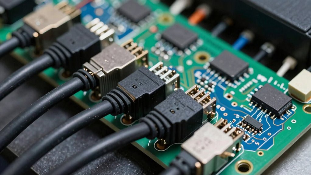
- Physical connection problems like loose cables or poor grounding disrupt signal integrity, impairing data capture.
- Inadequate protocol understanding or improper synchronization can cause scanners to overlook or misread CAN bus messages.
If you’ve ever been overwhelmed by the complexity of CAN bus systems, you’re not alone. These networks are intricate, with multiple devices communicating simultaneously over shared lines. One common frustration is why some scanners miss data, leading to incomplete or inaccurate diagnostics. Understanding the fundamentals can help you troubleshoot these issues more effectively. At the core, CAN bus relies heavily on proper protocol analysis. When scanning for issues or reading data, you’re essentially interpreting signals that follow specific rules. If your scanner isn’t correctly analyzing these protocols, it might overlook vital information. Protocol analysis involves decoding the messages transmitted between devices, ensuring that each bit and byte aligns with the expected standards. When this process is flawed—perhaps due to outdated software or incompatible hardware—you risk missing crucial data packets, which can compromise diagnostics.
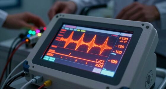
Signal integrity plays a pivotal role here. The physical layer of the CAN bus must maintain clean, stable signals for data to transfer reliably. Any electrical noise, poor grounding, or damaged wiring can distort signals, making them harder for your scanner to interpret accurately. When signal quality degrades, even if the data is transmitted correctly, your scanner might not recognize it or could misread it entirely. This is why ensuring proper wiring, shielding, and grounding is essential. If the signals are compromised, your device’s ability to perform effective protocol analysis diminishes, increasing the chances of missed data.
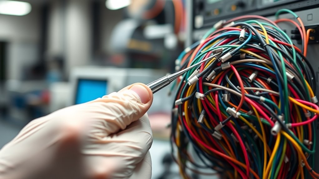
Additionally, proper timing and voltage levels** are crucial for accurate data interpretation. Many scanners depend on consistent timing and voltage levels to differentiate between logical states. Variations caused by interference or hardware faults can lead to missed or misinterpreted messages. For example, if the voltage drops below a certain threshold, the scanner might interpret a logical “1” as a “0,” or vice versa. This misinterpretation results in incomplete data capture and can make troubleshooting** more difficult. To avoid this, you should regularly verify your cabling and connections, ensuring that the physical layer remains solid.
In essence, the key to preventing missed data lies in maintaining signal integrity and conducting thorough protocol analysis. When both elements are functioning correctly, your scanner is better equipped to interpret all messages on the bus, providing comprehensive and accurate diagnostics. By paying close attention to wiring quality, shielding, grounding, and software updates, you’ll minimize the chances of missing critical information. Remember, a well-maintained physical connection combined with robust protocol analysis is the foundation for reliable CAN bus diagnostics—making your troubleshooting process smoother and more precise.

Advanced CAN Bus Diagnostics and Automotive Network Troubleshooting: Master OBD2 Systems, ECU Programming & Electrical Fault Analysis (Modern Automotive Technology Diagnostics Mastery Series Book 7)
As an affiliate, we earn on qualifying purchases.
As an affiliate, we earn on qualifying purchases.
Frequently Asked Questions
How Does CAN Bus Topology Affect Data Accuracy?
Your CAN bus topology directly impacts data accuracy by influencing signal integrity and communication reliability. A well-designed bus topology, like a linear or star configuration, reduces signal reflections and noise, guaranteeing accurate data transmission. Conversely, improper topology can cause data collisions and loss, decreasing accuracy. By choosing the right bus layout, you enhance data integrity, minimize errors, and ensure your scanner receives precise information from the CAN network.
What Are Common Hardware Issues Causing Missed Data?
Did you know that over 30% of data loss issues are caused by hardware problems? You might encounter missed data due to hardware interference, which disrupts signals, or connector faults that create poor connections. These issues can lead to inconsistent data flow, making it essential to regularly inspect and secure your CAN bus hardware. Addressing hardware interference and fixing connector faults guarantees reliable data transmission and reduces missed information.
How CAN Software Filters Improve CAN Bus Data Reliability?
Software filtering enhances CAN bus data reliability by allowing you to selectively process only relevant messages, reducing noise and eliminating unnecessary data. You can implement data validation to ensure incoming information meets specific criteria, catching errors early. This combination helps prevent missed or corrupted data, ensuring your scanner captures accurate, essential information. By fine-tuning software filters, you optimize system performance and improve overall data integrity.
What Are Best Practices for Troubleshooting CAN Bus Errors?
Troubleshoot technical CAN bus errors by systematically scanning for error codes using reliable diagnostic tools. Start by isolating issues with clear, consistent checks, then verify wiring and connections for wear or damage. Use diagnostic tools to read error codes, which reveal specific problems. Regularly clear and recheck codes to confirm fixes, ensuring your system stays stable. Staying methodical and meticulous minimizes mistakes, maximizing data accuracy and system reliability.
How Do Different Baud Rates Impact Data Transmission?
Different baud rates considerably impact data transmission, affecting both speed and data integrity. When you increase the baud rate, data transmits faster but becomes more susceptible to errors, especially over longer distances or noisy environments. Conversely, lowering the baud rate enhances data integrity by reducing errors, but it slows down communication. To guarantee reliable data transfer, select a baud rate that balances speed with the robustness needed for your specific CAN bus setup.

CANalyst-II USB to CAN Analyzer CAN-Bus Converter Adapter Support ZLGCANpro with OBD Plug
CANalyst-II USB to CAN Analyzer CAN-Bus Converter Adapter Support ZLGCANpro with OBD Plug
As an affiliate, we earn on qualifying purchases.
As an affiliate, we earn on qualifying purchases.
Conclusion
Understanding CAN bus basics can save you from missing critical data during diagnostics. By grasping how signals transmit and what can cause blind spots, you’re better equipped to troubleshoot effectively. So, next time a scanner misses information, ask yourself: are you truly reading the data or just skimming the surface? Mastering these fundamentals isn’t just about fixing cars; it’s about ensuring you don’t overlook what matters most. Are you ready to see the whole picture?

CAN LIN PWM Tester, WOYO PL007 CAN Bus Analyzer for Automotive Diagnostic Tool, Auto-Recognize CAN-H & CAN-L, CAN Range 50-1000kbps, PWM Signal Detector on Bench, LIN Bus Baud Range 2400-19200bps
CAN Mode: Automatic regonize the direction of CAN-H and CAN-L, can read CAN BUS Baud Range: 50, 83,…
As an affiliate, we earn on qualifying purchases.
As an affiliate, we earn on qualifying purchases.